The oil system in a VW engine is, like any vehicle’s engine, crucial to proper operation. The oil system of the air-cooled VW flat-four engine is even more important than one might realize since along with the primary lubrication function, the oil also serves a critical cooling purpose, with some of the oil being directed through the oil cooler located in the fan shroud.
It basically follows the following routing, with almost all activity occurring on the cylinder 3-4 side side of the case:
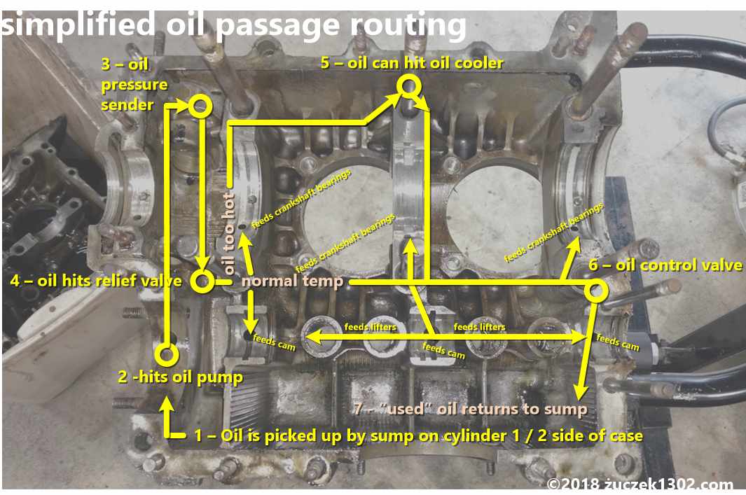
- The oil is picked up at the sump pick-up on the cylinder 1-2 side of the case.
- It travels through the oil pump (which of course caused it to be picked up in the first place) and heads to the top of the case
- It passes the oil pressure sender (connected to the idiot light on the speedometer)
- The oil then passes through the Oil Relief Pressure valve, and depending on the temperature and viscosity of the oil, goes through 2 possible routes. 1) The main route for low/normal temperature oil is the most needed route through the gallery feeding the crankshaft bearings, camshaft bearings, and the lifters (which then take it up through the push rod tubes to feed the rocker arms which then can flood back down the pushrod tubes back to the sump. If the oil temperature is too high, the Oil Relief Pressure valve can 2) sent up up to the top of the case in which it hits…
- The oil cooler and is routed up through the cooler with the fanshroud dropping the temperature, and hence the viscosity, of the oil.
- Both the gallery from the oil cooler and the main gallery feeding the crank/cam shafts join up before hitting the Oil Control Valve which ultimately deposits that oil path down through a port where,
- The spent/used oil is accumulated again where it then gets picked up by the sump siphon restarting the process.
One of the best pictures I could find… well… the only picture I could find of the case cut-away to actually show the oil gallery passages along the main axis is from The Samba member Jimmy111 posted way back on Jun 04, 2008 (image below)

You can clearly see the front to rear and top to bottom oil galleries clearly as well as the “tubes” for the front Oil Relief Valve and the rear Oil Control Valve. Within the galleries you can see the holes leading to the pathers that feed the camshaft and crank.
Once you see how these tunnels snake through the alloy of the case, it becomes apparent that without pulling the oil plugs on the external part of the case you just cannot ensure that all of these passages are free of debris completely clean of sediment or other deposits.
Sure, the solvents sort of washed through these. And yes, you can try to force high temp/high pressure water through these as well as compressed air, but there’s no real access to any of these without truly prepping the case prior to build to allow for access.
Here’s a video I found posted on YouTube by guidoguitar that helps to explain the paths too:
Sources:
Article – Gene Berg – About Oil Coolers » About Oil Coolers – Technical Info
Video – guidoguitar – Oil Pathways and Flows in VW Dual Pressure Relief Case. July 6, 2015
Article Thread – The Samba – Member Jimmy111 – Dual relief oiling system. How it works. February 17, 2008
Article – Bob Hoover – HVX MODS, May 29, 2007
I’m afraid I’m too much an amateur mechanic. What’s interesting is that you said it did not do this, and then it started. This of course implies something else may have changed which is resulting in this.
I have no experience with higher displacement engines and additional sump storage so I’m not sure how all that would come into play.
Great info, thanks for sharing. I have a 64 beetle with a 1600 pushed up to 1915. I’ve been having an issue with oil pressure, which I believe is contributing to a higher engine operating temp. After coming across your page, I figured what the heck, maybe you’d have some insight on the issue I’m struggling with.
The primary symptom being the oil pressure light illuminates at low RPM. On a cold engine start up, the light will flicker slightly on start up, then full extinguish after about 5-10 seconds. As long as the engine is operating above idle, the light stays out.
Once I back off the throttle, for example coming to stop at an intersection, the light will again flicker. At this point if I rev the motor, the light will again extinguish. Sometimes it will stay out, other times it will illuminate again after the RPMs return close to idle.
Now to add a plot twist to the scenario, as the engine/oil temp increases, the symptoms become more pronounced.
The motor didn’t always do this. And I didn’t change anything to create the condition. I didn’t build the motor myself, so I don’t have many details on what components were installed. I do run a 40 or 50 weight non-synthetic oil. I haven’t done anything to change the configuration of the motor. I have pulled, cleaned and inspected the pressure relief plunger of the crank end of the motor. I have also pulled and inspected the sump plate of the extended sump. I didn’t find anything significant during either procedure.
That’s a lot, but so far, no one has helped me figure this out. Figured I’d give you a shot.