
I started the long awaited engine removal process today.
This is the first time I have removed most of these parts on Murbella, and on the whole, the preparation for removing an original 75-79 Fuel Injected (FI) engine from a Beetle has a quite a lot more prep work than the pre-75 carb engines.
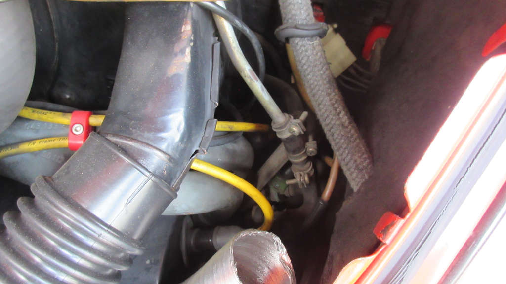
Some parts have to come off to just have space to access all of the connections from the main wiring harness as well as the FI harness, which as both independent of one another.
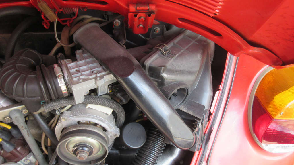
Most of the space over the 1/2 Cylinders is taken up by the Air Intake and Filter Housing and Air Flow Meter. All of this needs to be removed to access the FI harness wiring, as well as all of the vacuum hose connections for the emissions canister, and the alternator wiring points.
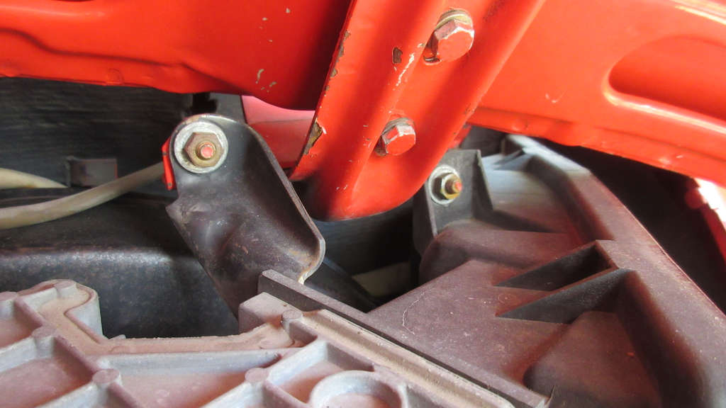
The Air Intake and Filter Housing unit actually mounts to the decklid hinge on this side by 2 10mm nuts and washers. It isn’t heavy, but this both keeps it all in place on the engine but makes basic quick works a bit more complicated if you want to get to things on this side.
The Air Flow Meter is situated between the Air Intake and the Air Intake Book Elbow. The FI wiring harness has a connection point here that must be removed.
Once disconnected and the 2 nuts at the decklid mount are removed, there is 1 clamp on the Air Intake Boot Elbow that must be loosened where it attached to the throttle body intake.
The entire assembly of 3 parts cane come off as one, or each part can be disconnected from one another.

Honestly, with this assembly gone, the engine looks just a bit closer to what Pre-1975 US carbureted engine looks like with the various vacuum lines and other wiring just all over the place.
The wires to the alternator can all be disconnected, as well as the other parts of the FI harness to the throttle body.
Thankfully, the harness connectors and what they connect into are all color coded for very easy identification.
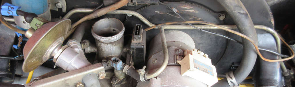
The fuel delivery rail can now be clearly seen (above) as it goes to each intake manifold and the injectors, as well as a 5th injector in the form of the Cold Start Valve (center above).

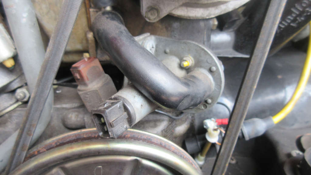
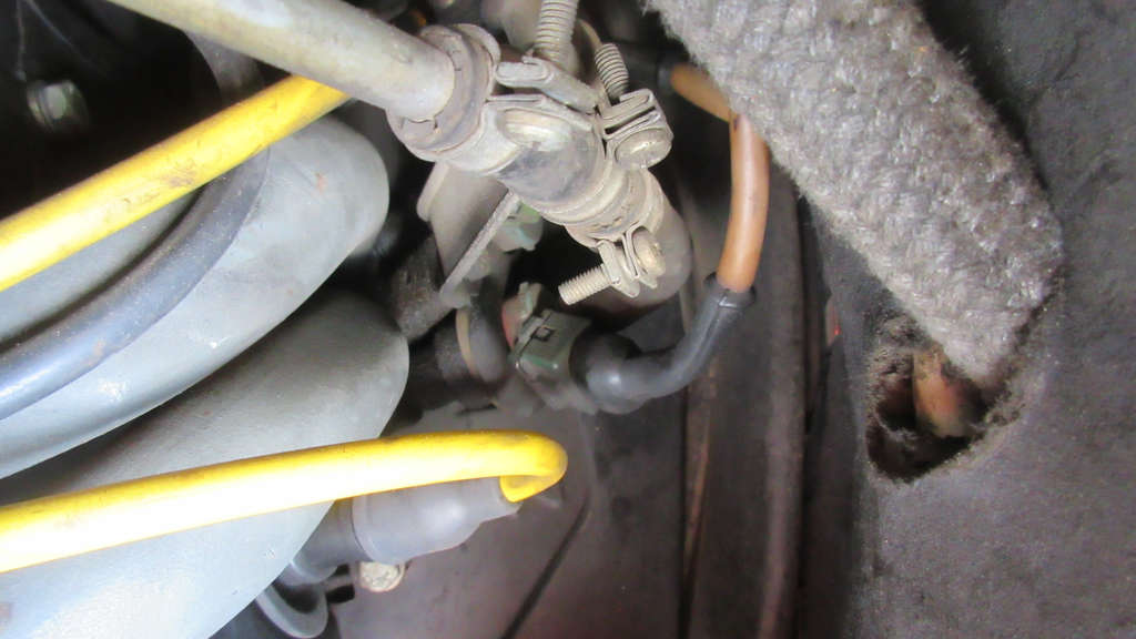
Mounted to the decklid hinge on the Cylinder 3/4 side is the Decel Valve. There are 3 vacuum hoses here that must all be disconnected.
There is one smaller hose that connects to the outer side and drops down to a T that splits into the EGR Valve and then goes down to the plenum.
One of the larger hoses on the opposite inner side of the decel valve drops down to the plenum on the throttle body.
The larger hose on the bottom of the valve then connects to the a T intake on the Air Intake Boot Elbow.
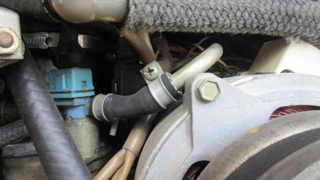
For the most part, the alternator on the FI engine is more or less identical in setup to the Pre-75 carb models. However, it is internally regulated and does not require the external regulator connection typically found under the rear seat of older alternator and generator configurations.
All of the wiring connections feed to the main wiring hardware.
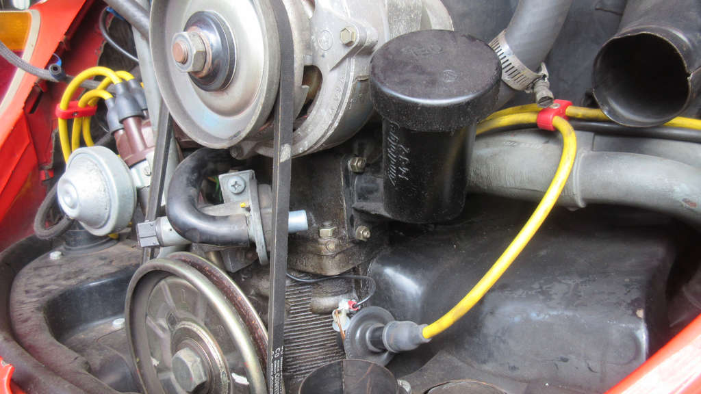
One big difference is that since the FI engine has a throttle body and plenum setup that is quite large, the alternator stand is substantially different and incorporates a plastic oil filler in the general location it would be on Pre-75 carb engines.
The metal strap to lock the alternator down to the stand is a bit more robust than the older styles ones.
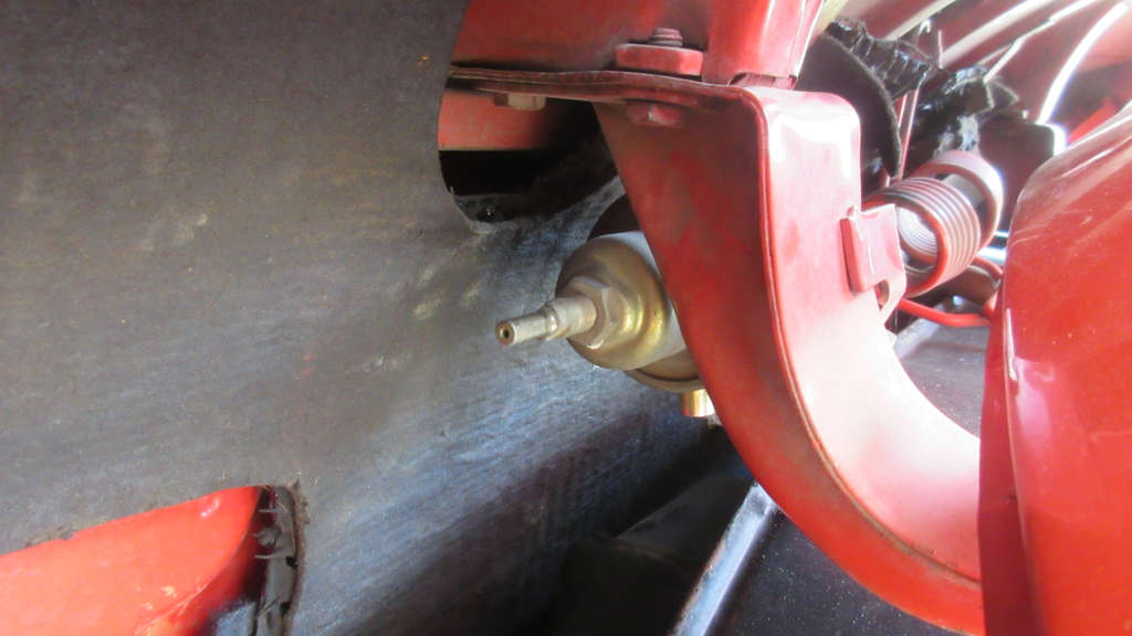
There’s no mechanical fuel pump on a Type 1 FI engine. In fact, the AJ case itself is completely redesigned form earlier carb cases and you cannot even put on on it. All fuel pump activity is handled by an high pressure electric fuel pump that is mounted under the fuel tank up front on the passenger side. This is also where a much larger fuel filter is connected prior to fuel being delivered to the rear lines and fuel array.
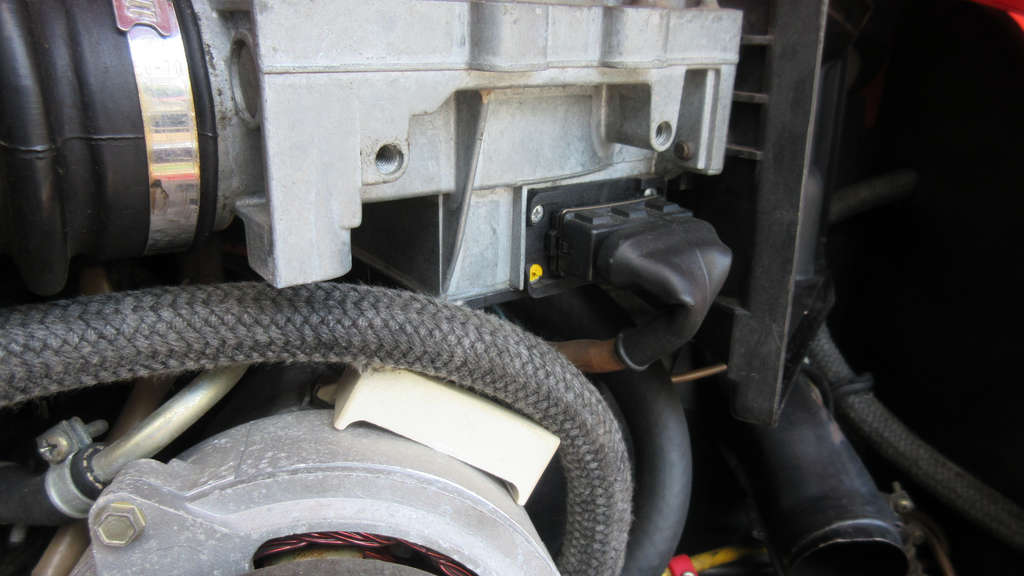
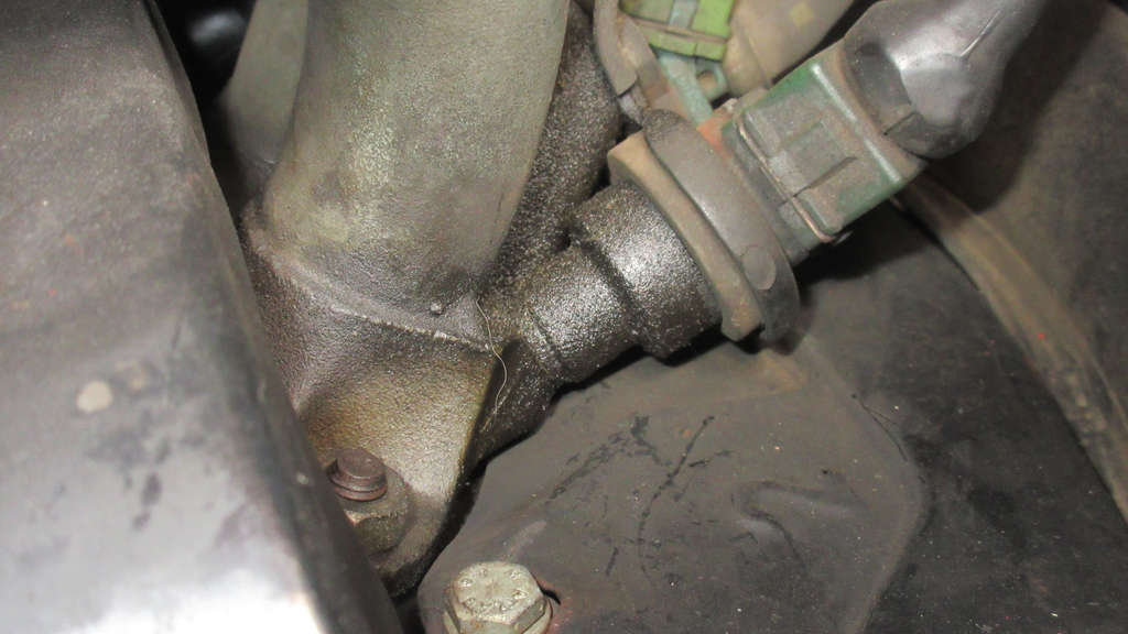
In the general location where the mechanical fuel pump would be, part of the FI system known as Auxiliary Air Valve exists and mounts to the bottom of the throttle body assembly.
This valve has a loom connection as well as various hose connections. When the engine starts up, this valve provides air directly into the throttle body (along with the fuel from the 5th injector). This valve controls the amount of air. There’s an additional hose that connectors the to T on the Air Intake Boot Elbow.
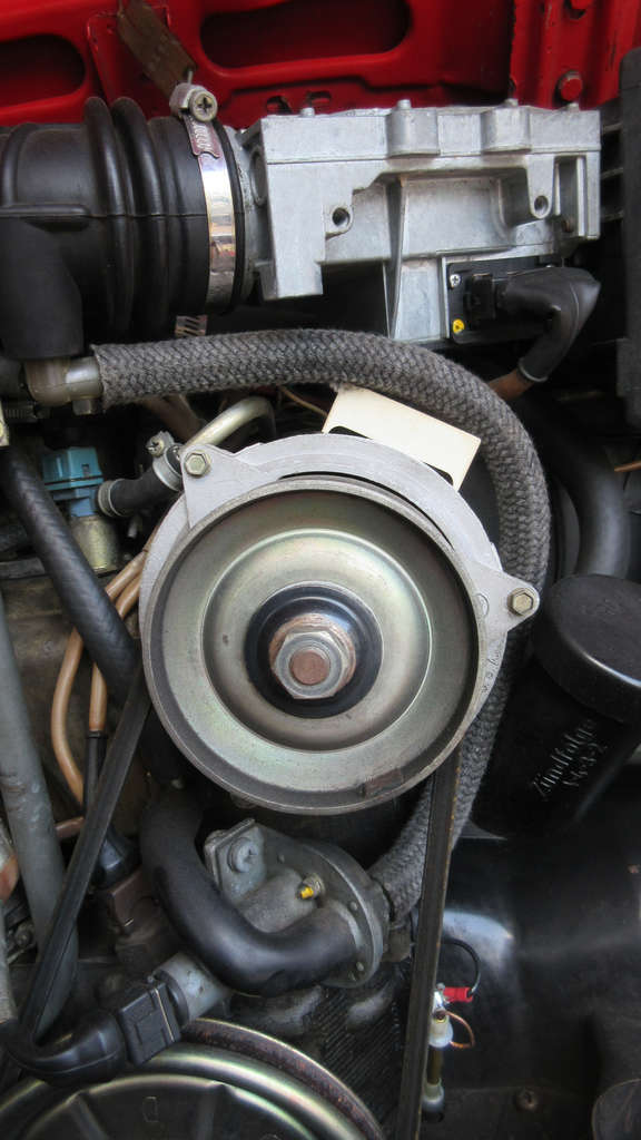
Compared to the earlier carb engines, there are so many hoses and vacuum lines to keep track of.
The valve’s harness connection point actually juts out above the crank pully and the alternator belt goes around the whole system. Proper clearance needs to be maintained around all of these parts so that the belt does not risk any contact.
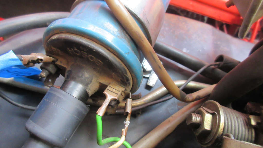
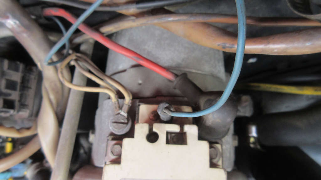
The coil is mounted in the traditional location on the fan shroud facing down and has many more connections at the various terminals than earlier engine setups.
The positive (15) terminal feeds the usual suspects such as the oil pressure gauge and wiring harness. The negative (1) connects the distributor and other lines.
Quite frankly, this entire part of the engine bay is so very cluttered with multiple wires going to and from to coil, the main spark plug wires from the distributor, and so many hoses and vacuum lines everywhere.
I am not sure if it is possible to really clean this area up. I mean, cable times might be helpful to some degree.
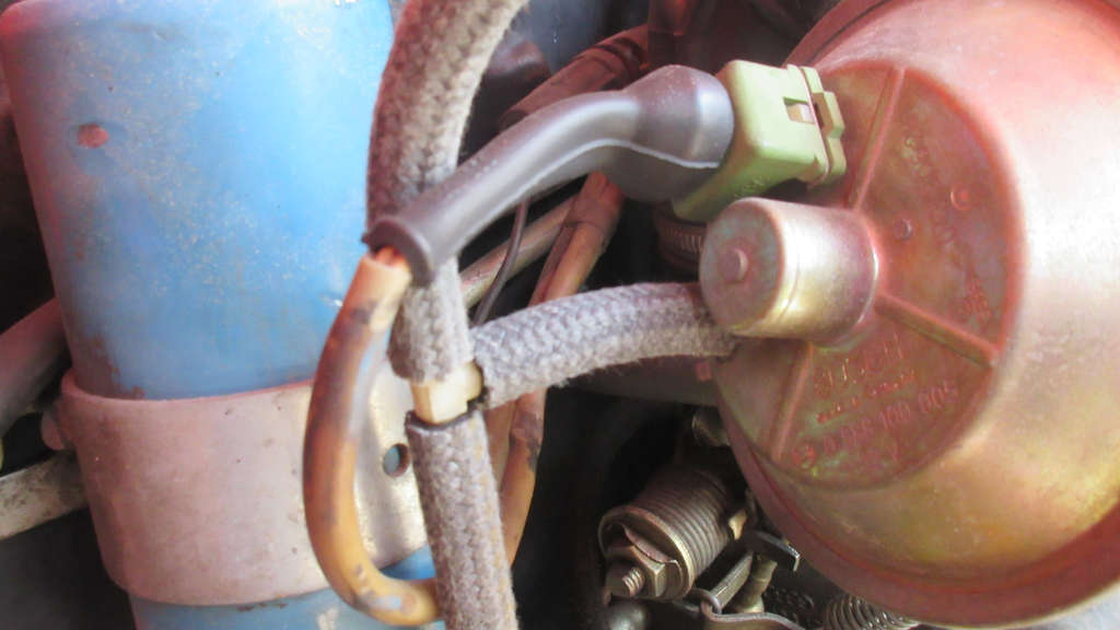
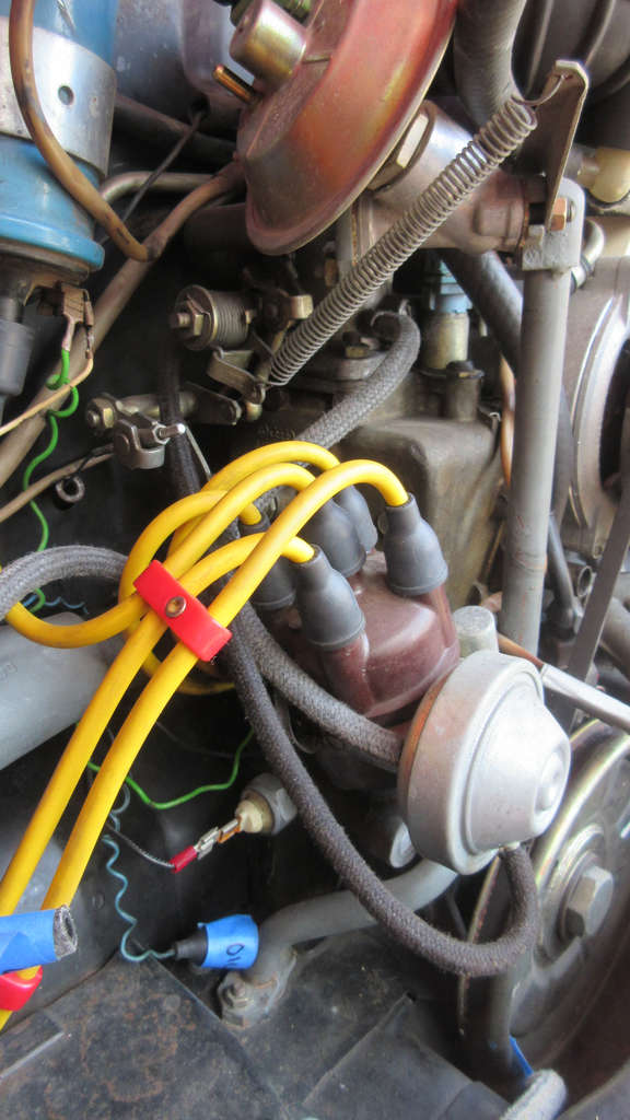
The 1975-79 Type 1 FI engines came with a 043905205H Bosch DVDA distributor (0 231 176 044).
The retard connection hose connects to a port at the bottom front part of the plenum next to the idle adjustment screw.
The advance connection hose connects to a port above the throttle.
The 205H DVDAs use share some replacement parts #s with similar era Bosch VW distributors:
- Points 01011
- Condenser 02074
- Cap 03010
- Rotor 04033
- Canister 07114 (all but impossible to find)
I had wanted upgrade to electronic ignition but of course, Pertronix and other vendors in the aftermarket do not make any points-replacement style upgrades specifically for the 205H that they will clearly state works with the FI engine setups. That of course, sucks.
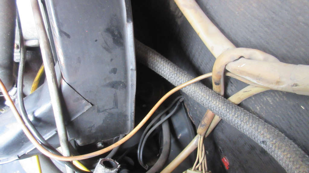
For the most part, with the top parts removed and the wiring harnesses freed up, it is fairly easy to inspect the fuel injectors and fuel lines for Cylinders 2 and 4.
Now I know that somewhere along the 1/2 fuel rail, and quite possibly the injectors themselves, is where the massive fuel leak started last year.
It was clear that high pressure fuel was coming out somewhere on this side of the engine.
I can’t tell if the residue above is an indicator that this is the source or not, but there is grime and fuel residue all around these parts.
All of these injectors will come out and be sent away for inspection and testing. All seals and rubber will be replaced.
While I can’t see any clear cracks in any lines either on the main 4 injectors or the 5th one (cold start valve) I have to admit there are a ton of tiny bits of fuel line on all these parts and then of course, they all have 2 clamps as well.
All of the soft lines and clamps will be replaced but I am not looking forward to all this minute work.
While Injector 2 and 4 are somewhat accessible, 1 and 3 are far more difficult to access with the engine in the car. None of these will be touched until later anyway when it is fully removed.
Another major difference on the FI engine is with the fan shroud.
It is redesigned from the Pre-75 carb ones, with the fresh air outputs slightly different, the inclusion of the velocity ring around the fan intake (at the rear) and the emissions canister connection is not on the side of the shroud but on an angle at the rear (above).
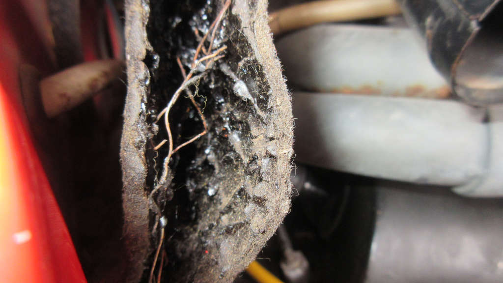
I have never seen a Beetle with a decent original Tar Board Insulation intact.
Most of Murbella’s is in good shape, especially on the passenger and rear body side, but the driver side part over cylinder 3/4 is falling apart.
I have a replacement, but I can tell you that it is not as nice as what I am replacing and perhaps I can just replace the damaged portion.
The original tar board from the 79 car has metal strands running through it providing vertical support and shape.
I almost wonder, with the engine out and the ability to easily remove these… can I actually repair these? I’d much rather try and get this back together, clean it up, and reinstall it than use that far more flimsy aftermarket one I bought.
Things I Need To Do
Based on today’s disassembly work there are some key things I did not take into account that I probably should do as I go over every part. This will cost additional money but I think some of these items will be necessary.
- Determine the best course of action in cleaning the wiring harnesses to preserve their plastic sleeves and connection points.
- Determine if the various plastic T connections on the hoses are still viable and not brittle.
- Consider cleaning exterior of alternator and if possible, replacement of internal bushings. Paint it aluminum color?
- Explore options for cleaning plenum/throttle body assemble and possibly painting.
- Consider options for cleaning 205H distributor and possibly painting vacuum can to deal with heavy aluminum pitting issues.
- Determine what is safe to use to clean sensor in Air Meter of this age.
- Should I get a brand new Bosch coil and use this existing one as a backup?
- Measure OD/ID of all of the many hoses and vacuum lines and completely replace with modern rubber or, if possible, new German braided rubber ones.